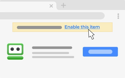
Pin or enable your RoboForm extension.
Pin the extension
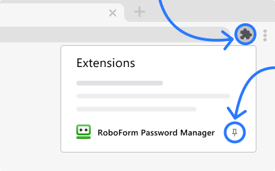
or
Enable
Use small C (10 pF - 100 pF) and small R ( Supply Voltage ( VCCcap V sub cap C cap C end-sub ): The frequency changes slightly if VCCcap V sub cap C cap C end-sub changes. For stability, use a regulated 5V source.
Frustrated, Lucas realized the textbook formula had failed him. The "k" factor—the constant that accounts for the hysteresis of the Schmidt Trigger—wasn't a fixed number. It changed based on voltage, temperature, and the specific manufacturer of the chip. He needed a way to predict the behavior without spending all afternoon swapping components.
They opened a Python IDE. Lucas started typing the standard formula: 74hc14 oscillator calculator
The internal thresholds of CMOS gates shift with ambient temperature. As the chip warms up, the hysteresis window can narrow or widen, causing minor frequency drift. Step-by-Step Design Example
with a series combination of a small fixed resistor and a potentiometer to allow fine-tuning of the output frequency. Use small C (10 pF - 100 pF)
$$ f \approx \frac1RC \cdot \ln\left(\fracV_T+ (V_CC - V_T-)V_T- (V_CC - V_T+)\right) $$
"The problem," Elena noted, "is that datasheets don't give you a fixed $V_T+$ or $V_T-$. They give you a range. For a 5V supply, $V_T+$ might be $3.0\textV$, or it might be $3.6\textV$. That variance completely changes your frequency." The "k" factor—the constant that accounts for the
For driving heavier loads, use a second gate of the 74HC14 to buffer the output of the oscillator. 7. Summary of Component Relations Component Value Impact on Frequency Increase R Decrease frequency (Slower) Decrease R Increase frequency (Faster) Increase C Decrease frequency (Slower) Decrease C Increase frequency (Faster)
T=K⋅R⋅Ccap T equals cap K center dot cap R center dot cap C
A calculator gives a theoretical number. Real-world performance requires trade-offs.
Actually, the standard textbook connection: